Showing posts with label Op amp. Show all posts

Sunday, March 25, 2012

Automatic Street Light Controller Circuit Diagram


This circuit is an automatic street light controller. Sensors used to detect changes in light is LDR (Light dependent resistor), the working principle of Light dependent resistor is exposed to light when the resistance value of LDR great, but if not exposed to light or dark then the resistance value of LDR.

LDR is a special type of resistance whose value depends on the brightness of the light which is falling on it. It has resistance of about 1 mega ohm when in total darkness, but a resistance of only about 5k ohms when brightness illuminated. It responds to a large part of light spectrum.
When light falls on the LDR then its resistance decreases which results in increase of the voltage at pin 2 of the IC 555. IC 555 has got comparator inbuilt, which compares between the input voltage from pin2 and 1/3rd of the power supply voltage. When input falls below 1/3rd then output is set high otherwise it is set low. Since in brightness, input voltage rises so we obtain no positive voltage at output of pin 3 to drive relay.

Sunday, June 12, 2011

IR Remote Control Circuit using Op amp 741


IR circuit is called Infrared Circuit. Remote controls are very much popular now-a-days. It is specially called cordless circuit. This circuit is very simple and low cost cordless remote control circuit which is based on infrared   rays.

Figure 1 shows the transmitter circuit. The transmitter produces infrared rays and that can be easily transmitted up to 4 meters with a special convex lens and a twin LED arrangements.
Figure 2 shows the receiver  circuit. Op amp IC1-741 generates high frequency squire wave which provides the gate pulses for SCR1. IC1’s output current flows through  SRC1 and it is conducting current and enables the LED to emits infrared rays. The output frequency of Op amp IC1 depends on the variable resistor VR1, which in turns varies the output radiations of the LED.


When IR rays fall on the photo-transistor T1 of the receiver, then base of the photo-transistor’s base produces charge carriers at a rate depending on the rate of arrival of incident radiations at the pn junction of the transistor. Then the resulting emitter voltage is amplified by Op amp IC-2 . The amplified signal is rectified by D2. Finally the amplified signal is to drive the relay.

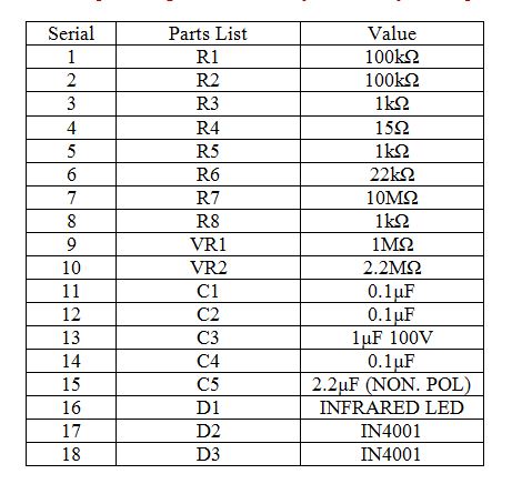
Parts List: