Showing posts with label IR rays. Show all posts

Monday, February 4, 2013

Remote Control Regulated Ceiling Fan Circuit Diagram

The main objectives are - to control the switch using remote as an on/off switch. To determine that the infrared sensor can easily receive the signal from the remote transmitter and to control the Fan speed using regulator.
The 38 kHz infrared rays generated by the remote control are received by IR receiver. Pin 2 of IR is connected to ground, pin 3 is connected to the power supply through R1 and the output is taken from pin 1. The output pulse is set to pin 2 of 555 timers.
Then in pin 2 if the voltage is less than one third of Vcc, a trigger pulse is active.The pulse signal is fed to clock pin 4 of counter IC 74109. Pin 8 of 74109 IC is grounded, pin 16 is connected to Vcc and pin 3 is grounded. The output of 74109 IC is taken from its pin 7. Q1 connected to pin 7 through R3 of IC 74109 drives the relay RL.

The relay is connected through a fan and a regulator.  It gets connected to live terminal of AC mains via normally opened (N/O) contact when the relay energizes. If we want to operate a DC 12 volt relay then we have to use a regulated DC 12 volt power supply for DC 12 volt Relay and we have to remember that the circuit voltage not be exceeded more than DC 5 volts.
Fig: Layout of Remote control regulated Ceiling Fan

JK flipflop/IC 74109:
The 74109 are dual positive-edge triggered, JK  flip-flops with individual J, K inputs, clock (CP) inputs, set (SD) and reset (RD) inputs; also complementary Q and Q outputs.The set and reset are asynchronous active LOW inputs and operate independently of the clock input. The J and K inputs control the state changes of the flip-flops as described in the mode select function table. The JK design allows operation as a T-type flip-flop by tying the J and K inputs together. In the T Flip-flop sequentially if the i/p is 1, the o/p is 1, then o/p is 0 and again 1.

Sunday, June 12, 2011

IR Remote Control Circuit using Op amp 741


IR circuit is called Infrared Circuit. Remote controls are very much popular now-a-days. It is specially called cordless circuit. This circuit is very simple and low cost cordless remote control circuit which is based on infrared   rays.

Figure 1 shows the transmitter circuit. The transmitter produces infrared rays and that can be easily transmitted up to 4 meters with a special convex lens and a twin LED arrangements.
Figure 2 shows the receiver  circuit. Op amp IC1-741 generates high frequency squire wave which provides the gate pulses for SCR1. IC1’s output current flows through  SRC1 and it is conducting current and enables the LED to emits infrared rays. The output frequency of Op amp IC1 depends on the variable resistor VR1, which in turns varies the output radiations of the LED.


When IR rays fall on the photo-transistor T1 of the receiver, then base of the photo-transistor’s base produces charge carriers at a rate depending on the rate of arrival of incident radiations at the pn junction of the transistor. Then the resulting emitter voltage is amplified by Op amp IC-2 . The amplified signal is rectified by D2. Finally the amplified signal is to drive the relay.

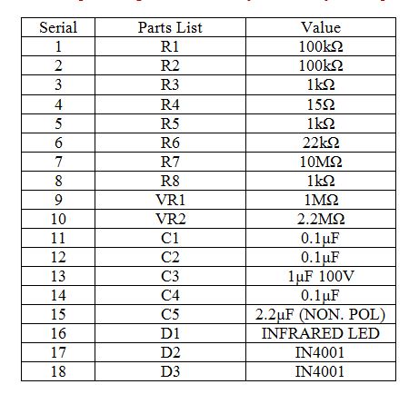
Parts List: