Showing posts with label LED. Show all posts

Sunday, June 12, 2011

IR Remote Control Circuit using Op amp 741


IR circuit is called Infrared Circuit. Remote controls are very much popular now-a-days. It is specially called cordless circuit. This circuit is very simple and low cost cordless remote control circuit which is based on infrared   rays.

Figure 1 shows the transmitter circuit. The transmitter produces infrared rays and that can be easily transmitted up to 4 meters with a special convex lens and a twin LED arrangements.
Figure 2 shows the receiver  circuit. Op amp IC1-741 generates high frequency squire wave which provides the gate pulses for SCR1. IC1’s output current flows through  SRC1 and it is conducting current and enables the LED to emits infrared rays. The output frequency of Op amp IC1 depends on the variable resistor VR1, which in turns varies the output radiations of the LED.


When IR rays fall on the photo-transistor T1 of the receiver, then base of the photo-transistor’s base produces charge carriers at a rate depending on the rate of arrival of incident radiations at the pn junction of the transistor. Then the resulting emitter voltage is amplified by Op amp IC-2 . The amplified signal is rectified by D2. Finally the amplified signal is to drive the relay.

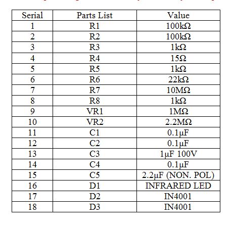
Parts List:
Friday, December 31, 2010

A Small project on Battery level Indicator


Battery level indicator is basically a design of light column voltmeter. It displays a column of light which height is proportional to the voltage. In the practical sense of view battery level indicator is used to show the voltage level of battery.
Working principle of this circuit is battery voltage compared with the reference voltage. This circuit is constructed by using 741 op-amp ICs. Op-amp is differential amplifier which output will be positive or negative, depends on the difference of input voltages.
When the input voltage difference is positive with respect to reference voltage and battery voltage, then the output is positive and the LED will emit light. If negative LED cannot emit light. It is the main principle of battery level indicator.
Voltage level indicated by the column of LEDs. For easy of reading LED rearranged in a vertical array. The top four LEDs indicates the battery voltage is high. Sequentially the lower level indicates the battery voltage is low and bottom four LEDs indicates very low voltage of the battery.
So, if the battery voltage continues to decline then LEDs will die in sequence from top to bottom.
In this circuit 1mA current is adjusted for reference voltage. Vcc is divided by the total number of resistor for finding the value of resistor R.
       
On the other hand, the resistor value of R1 is calculated by the equation,          


Component:
1. Op-amp IC 741
2. R = 3kΩ
3. R1 =220kΩ
4.  Diode 

Operation:
The voltage drop against the each resistor is 3 volt.
So when the Vin = 0v or less than 3v the output of all op-amp are at
–Vsat . The silicon diodes protect the light emitting diodes against excessive reverse bias voltage.
When Vin is increased to a value 3v to 6v, only the output of op-amp#1 goes positive  to light which indicate “Very Low”.
When Vin is increased to a value 3v and 6v, the output of op-amp#1 and  op-amp#2  are at +Vsat  and goes positive to light which indicate “Low”.
When Vin is increased to a value 6v and 9v, the output of op-amp#1, op-amp#2 and op-amp#3 are at +Vsat  and goes positive to light which indicate “Medium”.
Similarly, when Vin increased to 12v or higher, the output of all op-amps are at +Vsat  and all op-amps output goes positive to emit light of all LEDs which indicate “Full” .