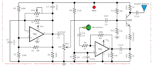
AM transmitter is a circuit which can transmit message signal to modulated signal. This circuit is designed with limited power and the required power supply of the transmitter circuit is 9 Volt.
The circuit has three parts that is an audio amplifier, radio frequency oscillator and modulator circuit. The frequency oscillator is built with 741 Op-amp and related components. The carrier signal frequency and its amplitude can be varied using variable resistor accordance with VR1 and VR2 respectively. C1 and C2 are the main components to generate the carrier frequency.
Another part of the circuit is an audio amplifier circuit. The audio amplifier is built with 741 Op-amp and related components. A microphone is used to convert the voice signal to the audio signal which is feed to the op-amp’s inverting terminal. This audio signal is amplified by the op-amp. The amplified audio signal is filtered using the capacitor C7. This output is feed to the modulator circuit.
The main part of the AM transmitter is modulator circuit which is built with the transistor BC109. The carrier signal is feed to the base of transistor and the message / audio signal is also feed to the emitter of the transistor.
Here the required modulated signal is taken from the collector of the transistor which is feed to the output antenna.

thank you so much it's very useful
ReplyDeletedoes this really work? if it is then. i'll be excited to make this circuit for educational purpose.
ReplyDeleteAn awesome work. Can you show the result of the audio amplifier, radio frequency oscillator and modulator as signal diagram?
ReplyDelete