Saturday, August 24, 2013

Line Follower Robot without Microcontroller


Today I am introducing a new project named - Line Follower Robot. Need not any microcontroller knowledge to make this project.

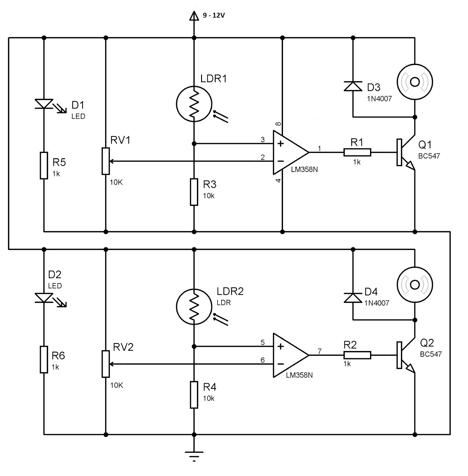
This is simple circuit where used LM358 Op-amp and the operated voltage is 9volt to 12volt DC. The LM358 contains two op amps which are wired as comparators. Thus the voltage at the inverting terminal (-) is higher than non-inverting terminal (+) the output will be low and when the voltage at the non-inverting terminal (+) is higher than inverting terminal (-) its output will be high.
Outputs of the op-amp comparators are given to transistors which are wired as switch to drive the motors. Diodes D3 and D4 are provided to cancel the negative voltages produced due to the back emf of the motor.

When a sensor is on white color, LED light will be reflected to the corresponding LDR. As a result, resistances of LDR decreases and the voltage at non-inverting terminal (+) of the op-amp will increase. Thus op-amp output goes high and turns on the transistor, which rotates the motor. When a sensor is on black color, LED light will not be reflected to LDR, thus the output of the op-amp will be low and the motor will be off.

Thus when the both sensor are on white color, it will run both motors forward and when any of them on black color it will stop the corresponding motor. Thus the robot turns in corresponding direction since one motor is running.
The sensitivity of the LDR can be adjusted by using the 10K pot. For more accuracy, cover the sensor-LED pairs in a black wrapper through sides in such a way that only the reflected light falls on the LDR. The Line Follower can trace path drawn with black ink on a white chart and the width of the black track should be a litte less than the width between sensors.

Saturday, June 15, 2013

Stepper Motor Rotation ( 172.5 degree angle ) without any Microcontroller

Stepper motor is an electronics device and a brushless DC electric motor that divides a full rotation into a number of equal steps. It is widely used in robotics, industry, computer peripherals, motion control, business machines and many other purpose. 

There are many techniques for rotating stepper motor. We need to rotate motor any angle that we want. We know that stepper motor is one kind of digital device or digital motor, for rotating this need sequential clock pulse to the specified coil of the motor. For rotating 360 degree angle need specific number of clock pulse which is depends on the number of coil and its mechanism. 
Most of the people use microcontroller for rotating stepper motor any angle and speed. Using microcontroller, stepper motor’s speed control and any angle rotation is very easy, accurate and flexible work. For microcontroller must need to know assembly or embedded C language. 

The students who are new or beginners, does not know these language is very difficult to make project related to stepper motor rotation. This topics will help them to solve the problem without having microcontroller knowledge. Because the topics is “stepper motor rotation any angle without microcontroller.” 

Though it is quite hard, students will be benefited by this hobby project. This project is fully hardware implemented and design is complicated on the clock IC section. The following project description is given bellow – 

Required instruments:
  1. Timer IC- 555 timer – 1pcs
  2. Flip-flop IC – 74109 - 1pcs
  3. Clock IC – 7490 – 2pcs
  4. AND gate IC – 7408 – 1pcs
  5. Jonson Counter – 4017 – 1pcs
  6. Motor driver IC – 293 -1pcs
  7. Relay – 6 volt – 1pcs
  8. Transistor – BC547 -1pcs
  9. Resistors – 150k, 10k and 1k - 2pcs
  10. Capacitors – 4.7 uF, 10nF
  11. Diodes – 4148 – 1pcs
  12. IC driver voltage – 5 Volt
  13.       Motor driver voltage – 9 Volt
Stepper Motor:
These stepper motor have 4 pin so have 2 coil. Pin-1 and Pin-3 have one coil. Pin-2 and Pin-4 have another coil. Motor have 48 steps so need 48 pulse for 360 degree rotation. So motor rotate 7.5 degree angle per step or per pulse. The stepper motor internal coil configuration is given bellow:
 So the pulse sequence will be Pin-1, Pin-2, Pin-3 and Pin-4. The stepper motor is connected to motor driver IC 293. 

Motor Driver IC:
For driving motor, need huge current. Jonson counter IC cannot deliver huge current to operate the stepper motor. For this reason motor driver ic is needed. IC293 is called motor driver ic which need 2 different voltage one is 5 volt and the other is motor driving voltage 9 Volt or 12 Volt.  Pin-9 will be connected to 9 Volt or 12 Volt and Pin-16 will be connected to 5Volt. Pin-1 and Pin-9 will be short and connected to 5volt with 10k resistor. Pin-4, 5, 12, 13 is connected to ground. Pin- 3, 6, 11, 14 are output and Pin- 2, 7, 10, 15 are input which are connected with 2nd Jonson counter IC 4017. 

Clock Pulse Generator:
This is the 555 timer based clock pulse generator which is called astable(free running) multivibrator. The output frequency is 1Hz which is fed to the Jonson counter (both IC Pin- 14) and clock IC (first IC Pin-14).
2nd Jonson counter (HC4017):
Jonson counter is a decade counter which have ten output pin and one input clock pulse pin. When clock pin-14 get pulse then the counter deliver pulse sequentially to the ten output pin. Here we need only 4 pin so the reset Pin-15 will be connected to Pin-10. So the four output pin of the counter are Pin-3, 2, 4, and 7 sequentially. Which will be connected directly with motor driver ic.
 N.B: Jonson counter ic driving voltage must be 5volt.

1st Jonson counter (HC4017):
Similar to 2nd Jonson counter only the difference is 1st Jonson counter’s output will be connected inversely to the 2nd Jonson counter’s output. Clock Pin- 14 of both ic will be connected to the clock pulse generator IC 555 output Pin-3.
N.B: Pin-16 of both IC are voltage pin connected to the 6 Volt relay. 6Volt relay supply the voltage alternatively to the two Jonson counter IC.

Clock IC (SN74LS90N):
SN74LS90N is mainly counter IC used for making digital clock in laboratory work that’s why it is popular as clock ic. Two 7490 are using here to get 23 pulses for rotating 172.5 degree angle. AND Gate IC (7408) is also used here. This circuit diagram is given bellow:

 N.B: If you need to know how it works please visit here. IC driving voltage must be +5volt if greater ic not work accurately.

Flip-flop (74109):
This is the  flip-flop IC which is configured as a T flip-flop. T flip-flop output depends on the input (which is come from the 7409 ic). Pin-2 and 3 is connected to the output of the SN74LS90N IC. And the output pin-6 is connected to the transistor BC547.
When input is 1 the output is 1 and when input is 1 the output is 0. Again
When input is 1 the output is 1 and when input is 1 the output is 0.

 If is most important that every 23th pulse clock IC(SN74LS90N) give one pulse. So the output of the Flip-flop will be 1 and 0 alternatively on every 23th pulse. Using this technique transistor will be ON and OFF according to Flip-flop output. And also active and de-active the relay alternatively.

Relay:
The main function of relay is to supply the positive voltage (+5volt) alternatively to the Jonson counters (Pin-16). When 1st Jonson counter (HC4017) will get the voltage, the motor rotate 172.5 degree clockwise direction and when 2st Jonson counter (HC4017) will get voltage, the motor rotate 172.5 degree anti-clockwise direction. 


Any Angle:
By changing clock IC pulses we can change the angle of the motor rotation.
Wednesday, April 10, 2013

Capacitor Code Calculator

Capacitor is a two terminal passive electrical component. It is used to store energy in an electrical field. Capacitor works as a voltage source.  The capacitor is used widely and its forms contains at least two electrical conductor separated by a dielectric material, one common construction consists of metal foils separated by a thin layer of insulating film. In electrical circuit capacitors are widely used as a parts. 
The static electric field develops across the Di-electric when the voltage or potential difference is applied across the terminals. This occurs when negative charge is on one plate and positive charge on the other plate. Mainly electrical energy is stored in the electrostatic field.  An ideal capacitor is characterized by a single constant value capacitance and measured in farads. So we need to know the measurements of capacitor value using the figure. For more information go wikipedia.

Monday, February 4, 2013

Remote Control Regulated Ceiling Fan Circuit Diagram

The main objectives are - to control the switch using remote as an on/off switch. To determine that the infrared sensor can easily receive the signal from the remote transmitter and to control the Fan speed using regulator.
The 38 kHz infrared rays generated by the remote control are received by IR receiver. Pin 2 of IR is connected to ground, pin 3 is connected to the power supply through R1 and the output is taken from pin 1. The output pulse is set to pin 2 of 555 timers.
Then in pin 2 if the voltage is less than one third of Vcc, a trigger pulse is active.The pulse signal is fed to clock pin 4 of counter IC 74109. Pin 8 of 74109 IC is grounded, pin 16 is connected to Vcc and pin 3 is grounded. The output of 74109 IC is taken from its pin 7. Q1 connected to pin 7 through R3 of IC 74109 drives the relay RL.

The relay is connected through a fan and a regulator.  It gets connected to live terminal of AC mains via normally opened (N/O) contact when the relay energizes. If we want to operate a DC 12 volt relay then we have to use a regulated DC 12 volt power supply for DC 12 volt Relay and we have to remember that the circuit voltage not be exceeded more than DC 5 volts.
Fig: Layout of Remote control regulated Ceiling Fan

JK flipflop/IC 74109:
The 74109 are dual positive-edge triggered, JK  flip-flops with individual J, K inputs, clock (CP) inputs, set (SD) and reset (RD) inputs; also complementary Q and Q outputs.The set and reset are asynchronous active LOW inputs and operate independently of the clock input. The J and K inputs control the state changes of the flip-flops as described in the mode select function table. The JK design allows operation as a T-type flip-flop by tying the J and K inputs together. In the T Flip-flop sequentially if the i/p is 1, the o/p is 1, then o/p is 0 and again 1.

Tuesday, November 6, 2012

IR Remote Control Home Appliance Circuit Diagram


This is the most popular IR Remote control circuit for home appliances like lamp, fan, radio, tv etc to make the appliance turn on/off from a TV, VCD or DVD remote control. It is very simple to build because of few components and simple design.
The circuit can activated from up to 10 metres. The 38kHz infrared (IR) rays generated by the remote control are received by IR receiver module TSOP1738 of the circuit. Pin 1 of TSOP1738 is connected to ground, pin 2 is connected to the power supply through resistor R5 and the output is taken from pin 3. The output signal is amplified by transistor T1 (BC558).

The amplified signal is fed to clock pin 14 of decade counter IC CD4017 (IC1). Pin 8 of IC1 is grounded, pin 16 is connected to Vcc and pin 3 is connected to LED1 (red), which glows to indicate that the appliance is ‘off.’ The output of IC1 is taken from its pin 2. LED2 (green) connected to pin 2 is used to indicate the ‘on’ state of the appliance. Transistor T2 (BC548) connected to pin 2 of IC1 drives relay RL1. Diode IN 4148 acts as a freewheeling diode. The appliance to be controlled is connected between the pole of the relay and neutral terminal of mains. It gets connected to live terminal of AC mains via normally opened (N/O) contact when the relay energises. you can use any NPN transistor inplace of BC548. You can also use SL100 or any NPN transistor lying around you.
The delay depends on the C1 capacitor. Using higher value capacitor will create more delay and using less value capacitor will switch the circuit more than 2 times when you press a remote. Analyse the circuit by placing the 10uf capacitor in place of C1 (100uf).