Monday, July 27, 2015

Blinking LED using PIC16F877A Microcontroller

LED blink using microcontroller is the first step for microcontroller programmer. It is quite easy for the students if he/she know the C programming. In this section you need to know the embeded C language for microcontroller programmin and also need the simulation software to test the .hex code. the simulation software neme is proteous professional that i used. Several tutorials will be found on youtube if you need to teach the operation and settings.

This was my first microcontroller project which have four LED blinkin secquentially.

Sunday, February 15, 2015

Tank Circuit and it's uses in Oscillator

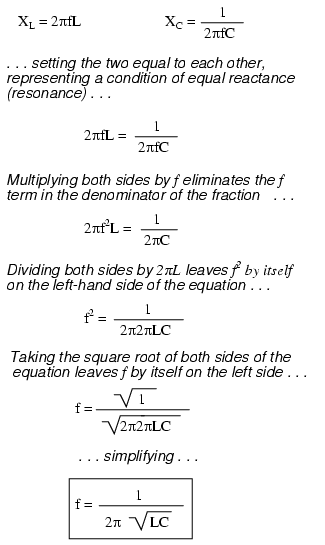
Tank circuit is basically made by an LC circuit. It is also called a resonant circuit, tuned circuit. It is an electric circuit consisting of a capacitor and inductor which is connected together.  Tank circuit can store energy by oscillating at the circuit resonant frequency.
 The frequency of the resonance tank circuit is given below where XL is the inductance -

Wednesday, September 24, 2014

Free Download Electronic Workbench 5.12 Full Version

When you are electronic student, maybe you will not foreign again with Electronic Workbench software or called EWB software. We think that this software very popular in electronic student because many electronic university or collage using Electronic Workbench to create electronic circuit and then simulate it easily.

When you using Electronic Workbench software to help your electronic project, you can draw electronic circuit schematic project using many tools that provided by EWB. You can choose many component that provided to draw your electronic project.
 
When you want to draw the schematic circuit, you can firstly choose components that needed one by one. And then you can adjust your component according your electronic schematic. You can connected your components one by one according the circuit easily. and then you can continue to simulate your project.

When you want to know how your project will work, you can choose many tools like AFG, Frequency Generator, etc. You can connected many measurement tool to your electronic circuit that drawing and then you can simulate your project to know the working of your circuit schematic.And it is will help you before you implemented your project to real project.


Friday, March 7, 2014

Memory Organization of PIC16F877A

The memory organization of a PIC16F877A chip is divided into three sections. They are -  Program Memory
  • Data Memory and
  • Data EEPROM
Program Memory is a data storage system. It is used to store program which is written by the
user.  The program counter executes these stored commands one by one. PIC16F877A device
have 13 bit wide program counter and it is capable of addressing 8K×14 bit program memory
space. This memory is used to store the programs that are written primarily. This memory is
also called Flash Memory.

Data Memory contains a special register like Special Function Register (SFR) and General
Purpose Register (GPR). Data memory is called Random Access Memory (RAM). The stored
variable of program in data memory is deleted after turning off the microcontroller. These two
memories have separate data buses, which make the access to each one of them very easy.

Electrically Erasable Programmable Read-Only Memory is called EEPROM. It is user
modifiable read only memory (ROM) that can be erased and reprogrammed repeatedly through
the application of higher than normal electrical voltage. EEPROM has a limited life that is the
number of hundreds or thousands of times it can be reprogrammed. The life of the EEPROM
can be an important design consideration. A special form of EEPROM is flash memory which
uses normal PC voltages for erasing and reprogramming.

Friday, November 1, 2013

External Oscillator Modes for PIC Microcontrollers


External oscillator (EC) is made outside of the microcontroller and connected to the pin OSC1 and OSC2 as figure 4.3. The external clock (EC) mode uses external oscillator as a clock source. The maximum frequency of this clock is limited to 20 MHz. Mainly crystal oscillator is used in this purpose.
In this mode the microcontroller starts operation immediately after the power is on. No time delay is required for frequency stabilization.

Figure: External Clock Oscillator Mode with Quartz Crystal  

There are three modes as LP, XT and HS. Each modes are used on external oscillator as a clock source. The frequency is determined by quartz crystal or ceramic resonators which is connected to the OSC1 and OSC2 pins and depending on the features of the component in use. Any one mode is used on microcontroller circuits.
  • LP (Low Power) mode - is used for low-frequency quartz crystal only. This mode is designed to drive only 32.768 kHz crystals usually embedded in quartz watches. It is easy to recognize them by small size and specific cylindrical shape. The current consumption is the least of the three modes.
  • XT mode is used for intermediate-frequency quartz crystals up to 8 MHz. The current consumption is the medium of the three modes.
  • HS (High Speed) mode - is used for high-frequency quartz crystals 4MHz or greater. The current consumption is the highest of the three modes.